3. Data Transmission
- Serial
- Synchronous
- Asynchronous
- Isochronous
- Parallel
Parallel Transmission
- Send group of bits simultaneously using separate lines for each bit
- Pros
- Fast
- Cons
- Costly for long distances
- Bits may not be relieved simultaneously
Serial Transmission
- Serial: bits sent over a single line one bit after another
- Pros
- Cheap
- Reliable
- Cons
- Complex
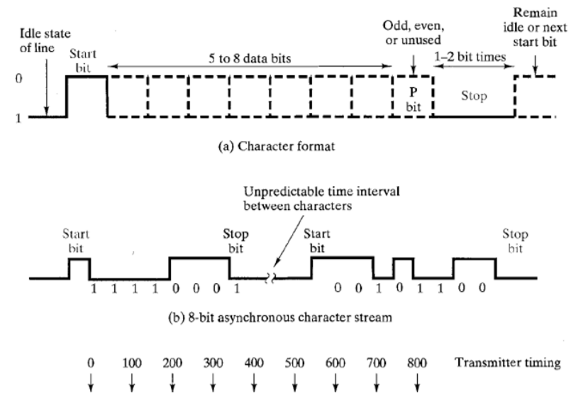
Asynchronous Transmission
- Bits are divided into groups and sent independently
- Receiver doesn’t know when the bits will arrive
- Unpredictable time intervals between transmissions
- Timing maintained within a group
- Must signal that the sender is going to send data before sending data
- Must signal that the sender has finished sending a group
- Cons: Too much overhead
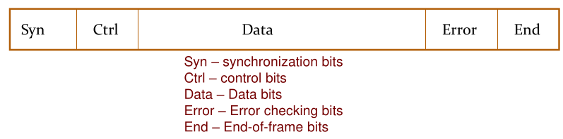
Synchronous Transmission
- Larger bit groups are sent without start/stop bits
- AKA: Frame
- Frame structure varies from protocol to protocol
Isochronous Transmission
- Combines both synchronous and asynchronous
- Sends blocks asynchronously
- Each transmission begins with a start packet. Once the start packet is transmitted, the data must be delivered with a guaranteed bandwidth
- Commonly used for places where there’s a time constraint, like streaming video
Simplex, Half duplex and duplex
- Simplex
- One direction
- Half duplex
- Both directions, one way at a time
- Full duplex
- Both directions, same time
Multiplexing
- Many to one
- Routes transmission from multiple sources to a single destination
- Two types
- Frequency Division Multiplexing
- Time Division Multiplexing
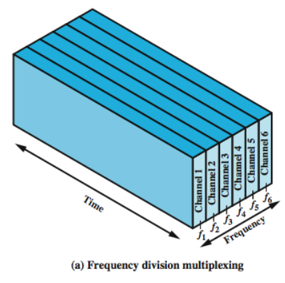
Frequency Division Multiplexing
- Useful when the bandwidth of the transmission medium extends the required bandwidth of signals to be transmitted
- Multiple signals can be carried simultaneously if each signal is modulated int a different career frequency.
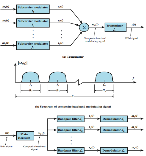
FDM Issues
- Crosstalk: May occur if the spectra of adjacent component signals overlap significantly
- Intermodulation noise: On a long link, nonlinear effects of amplifiers on a signal in one channel could produce frequency components in other channels.
Synchronous Time Division Multiplexint (TDM)
-
This is possible when the achievable data rate of the medium exceeds the data rate of signals to be transmitted
-
Multiple data signals can be carried on a single path by interleaving portions of each signal in time.
-
Interleaving can be at bit level or in blocks of bytes or larger quantities.
-
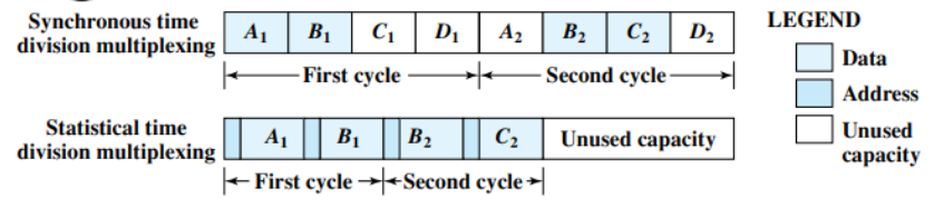
Synchronous TDM is called synchronous because the time slots are preassigned to sources and fixed. Time slots for each source are transmitted whether or not the source has data to send.
-
Flow control mechanisms are not needed for TDM. Data rate on the multiplexed line is fixed and the multiplexer and demultiplexer are designed to operate at that rate.
-
For error control, it would not request retransmission of an entire TDM frame. Error control will be handled on a per-channel basis.
-
For flow and error control, a data link control protocol such as HDLC can be used.
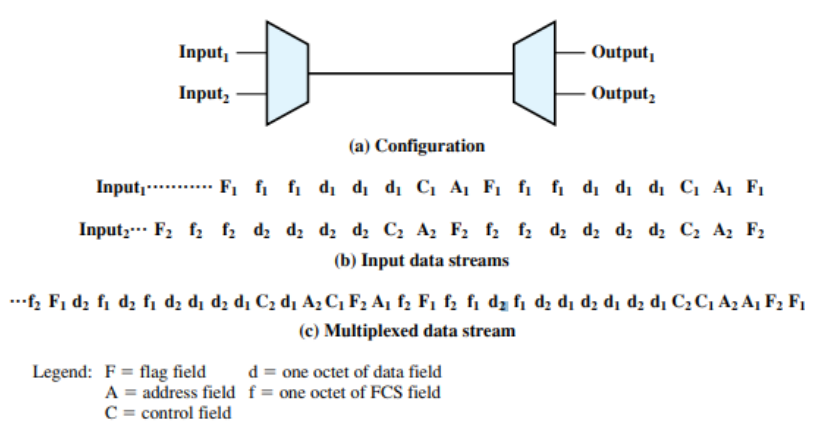
TDM Link Control with High-Level Data Link Control (HDLC)
Clock Synchronization Problem
- When multiple sources are combined into a high speed stream, most of the time, clocks of these sources may not sync properly.
- This can happen due to factors like clock drift, network delays etc.
- Pulse Stuffing is used to mitigate this problem
Pulse stuffing
- Set the outgoing multiplexed stream speed slightly higher than the maximum sum of the source streams
- Add extra dummy bits to slower streams to bring them upto speed
- These bits are inserted at fixed locations and removed at demultiplexer.
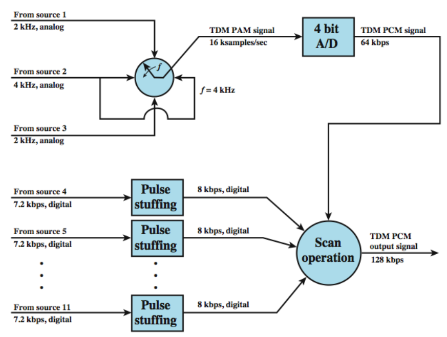
TDM Example
- Consider there are 11 sources to be multiplexed
- Analog sources are converted to PCM
- Pulse stuffing is used to raise each digital source to 8kbps
Statistical TDM
- In synchronous TDM, many time slots often are wasted.
- Alternative to synchronous TDM is statistical TDM
- statistical TDM dynamically allocate time slots on demand
- In this case, there are n I/O lines, but only k (k<n) tune slots available
- Multiplexer: scan input buffers, collect data until a frame is filled, and send it
- Demultiplexer: Recieve a frame, and distribute it to appropriate output buffers
- Statistical multiplexers can support more devices compared to synchronous multiplexers
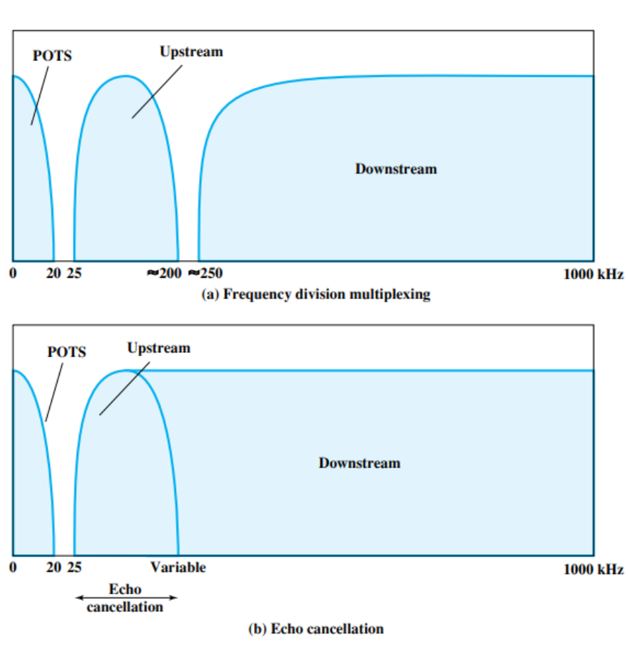
Asymmetric Digital Subscriber Line (ADSL)
- Make use of existing telephone line link
- Use frequency division multiplexing
- Reserve lowest 25kHz for voice AKA: POTS (Plain Old Telephone Service)
- Voice is carried only in 0 to 4kHz band, additional bandwidth is there to prevent crosstalk
- Use echo cancellation or FDM to allocate two bands for upstream and downstream
- Use FDM within upstream and downstream
Discrete Multitone (DMT)
- Uses multiple carrier signals at different frequencies, sending some bits on each channel
- On initialization, DMT modem sends test signals on each subchannel to determine the SNR
- Modem then assigns more bits to channels with better quality
- Available transmission band is divided into a number of 4-kHz subchannels
- Each subchannel can carry a data rate of from 0 to 60kbps
- At higher frequencies there’s increased attenuation and decreased SNR